

RiverSpy.Net : Online river level info for Irish kayakers
History of RiverSpy
RiverSpy v1
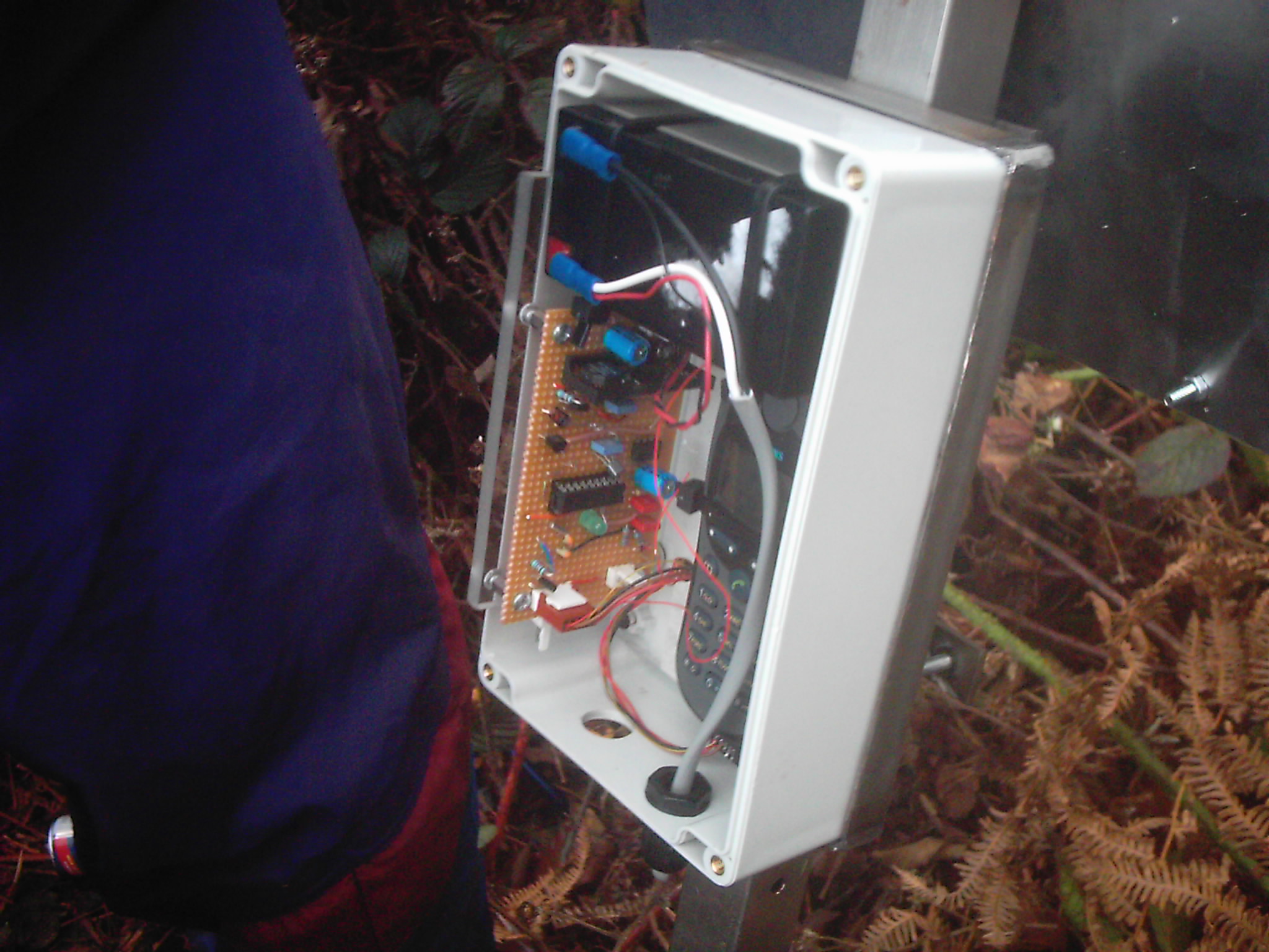
The project started in 2004 when development boards such as the Arduinos and Raspberry Pis of today were not available. The original system was based on the PIC16F88 micro-controller from Microchip. It came in an easy to prototype 18-pin DIL through hole package. This allowed it to be mounted easily in a socket. The original circuit was built on vero board. As well as the micro-controller, the board had a 4V-2A dc-dc module to power the phone, a 9V regulator with on/off to supply the underwater sensor, a watch crystal to keep time, an LED that flashed in various ways to provide debug information as well as a handful of capacitors and resistors.
Industrial modems were very expensive and power hungry devices in 2004 so the system communicated using an old Siemens M35 mobile phone. The battery was removed and the phone was powered by the 4V from the dc-dc on the circuit board. A fantastic feature of all Siemens phones of that era was that serial modem connections were included in the port at the bottom where the charger cable was connected. It had TX and RX pins that spoke standard 19200 Baud RS-232, the default way of talking to anything before USB came along and still in widespread use today. The outputs were at TTL levels and could be connected straight to the micro-controller or level shifted to connect to a PC or laptop.
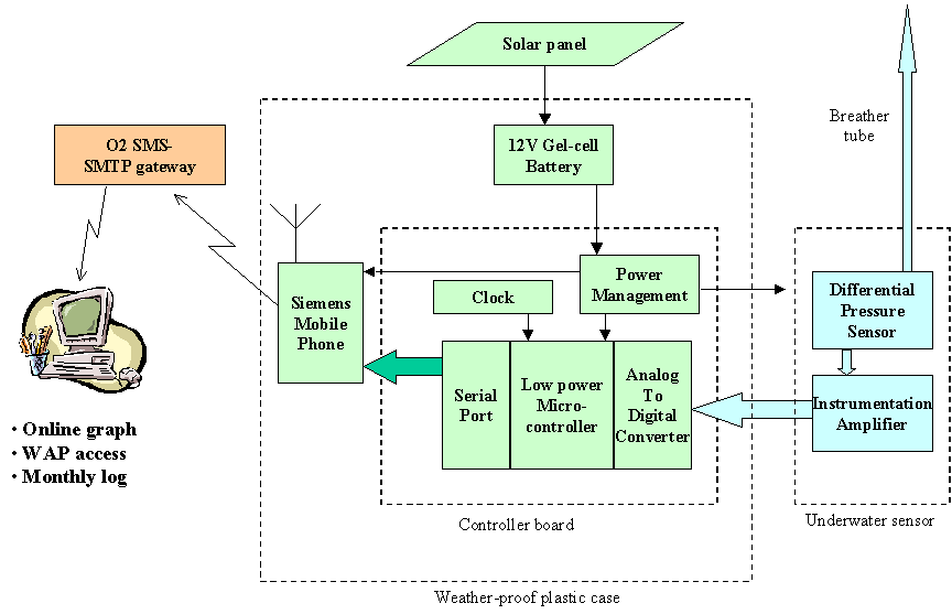
The box also contained a 12V lead-acid battery which was charged by a 12W solar panel. The system proved a little too power-hungry for the panel on dark days in the depths of winter so a car battery located at the base of the system was later connected in parallel with the small battery to keep the system going until the sun shone again.
The system measured the river level every 15 minutes and sent a single text message with a day's worth of data to the server every morning to be displayed on the web as a graph and could also be accessed via WAP for paddlers out and about. The phone numbers of approx 30 admins were also programmed into the system. If an admin rang the M35 phone, the system woke up, checked the number and if it was on the list, it then rejected the call and sent a text to the admin with the latest level and trend. Later a system of beeps were added so that if anyone else rang the system, the M35 would answer and play one tone for every 10cm of water on the river. An added bonus was that if it was raining heavily, you could also hear the raindrops bouncing off of the box. This all seems very basic now in the days of internet everywhere but in Glenbeigh 2004, when paddlers heard that could ring a phone at the Flesk river and it would text back the level, it caused a big stir.
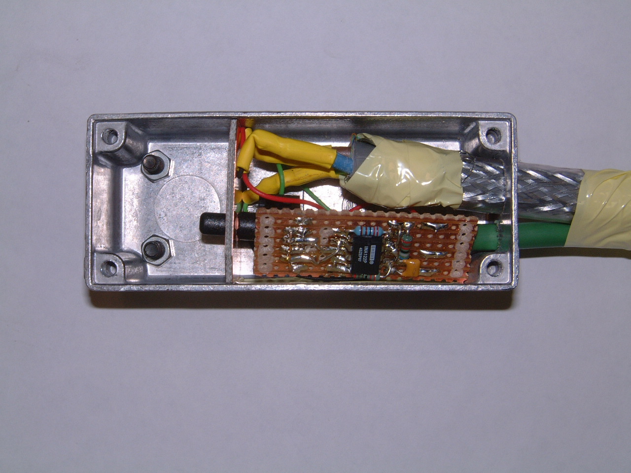
The underwater sensor part was also home made at the time. A plastic Honeywell differential pressure sensor was used to measure the difference in pressure between the bottom of the river and the air above. This pressure is the height of water times the density of water (1000kg/m^3) times g (9.81m/s^2). The voltage output of the pressure sensor is tiny so it was amplified under the water by an INA122 instrumentation amplifier (seen on the underside of the small pcb below). A length of plastic breather tubing was connected from one side of the sensor to well above the surface. The other side was open to the water via holes drilled in the left side of the metal box below. The right hand side, containing the electronics was filled with epoxy resin. A 3-core armoured cable carried 9V to power the sensor and amplifier, ground and a return signal between 0.2V and 7.5V. Unfortunately, the underwater sensor proved to be the Achilles heel of the system. The harsh environment of the Flesk caused the sensors to fail, typically after 12 to 18 months. Conversely, the more benign environment of the Liffey still has a homemade sensor in place and working after a number of years.
Riverspy v2
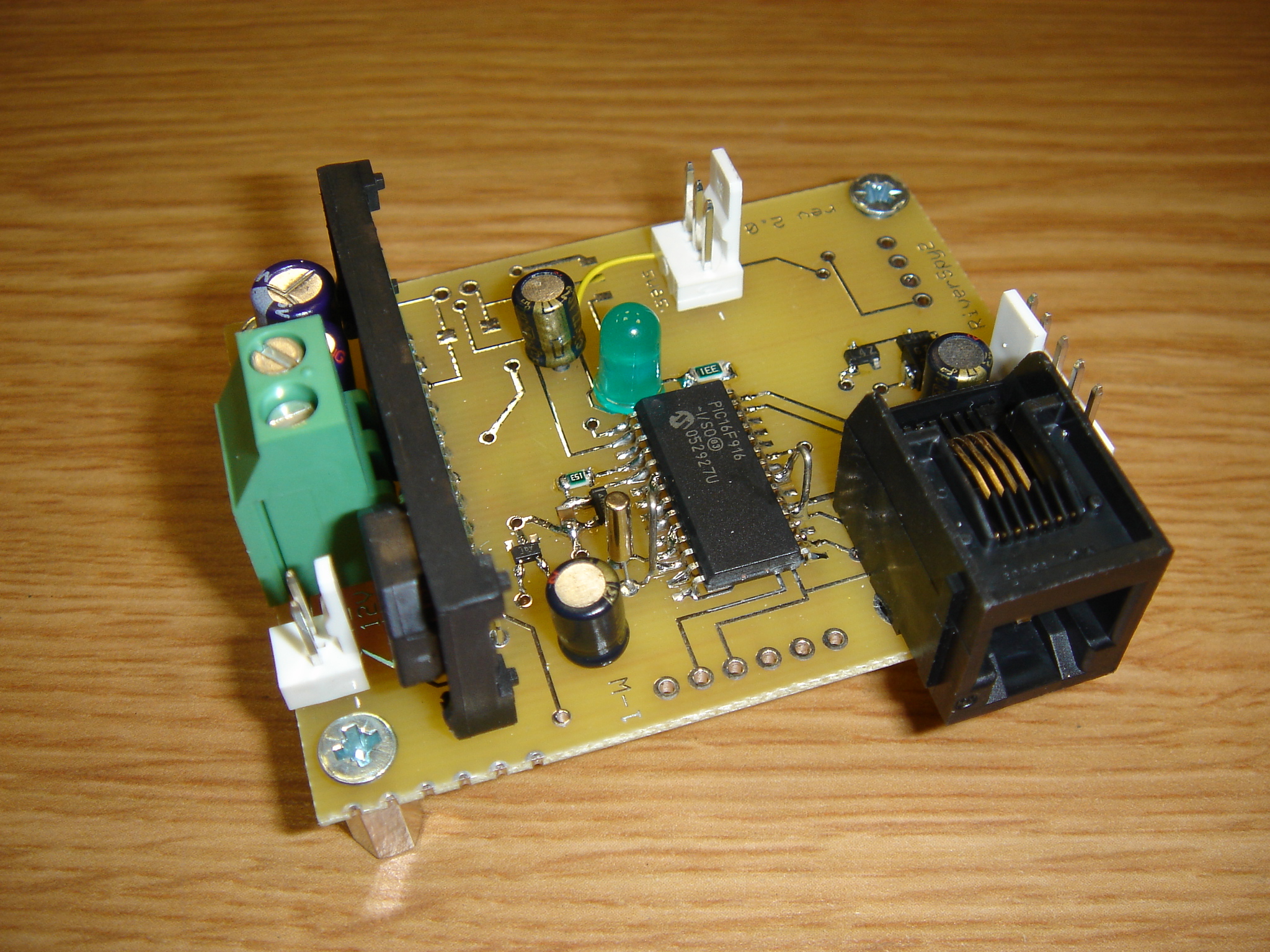
The original system went through a number of updates both in terms of hardware and software but remained at its core quite similar to version 1. A major limitation of the original system was the lack of memory on the micro-controller (7kb, about enough for a thumbnail picture). A better micro-controller of the same family later became available, the PIC16F916. This device had double the memory of the original device (now 14kb), allowing extra features to be added, in particular, the ability for everyone to be able to ring the system and hear a number of beeps corresponding to the level.
Version 2.0 was laid out as a custom printed circuit board. The RJ11 telephone connector is for connecting the system to in a Microchip ICD2 hockey puck to allow programming and debugging of the chip. The system on the Flesk still used the original M35 mobile phone though Mike Sweeney in UL did experiment at this time with using the Siemens T35 modem to make the system easier to wire and more reliable. (soldering wire-wrap wire to the connector at the base of the M35 required a very steady hand). The above ground portion of the system remained unchanged between around 2005 and 2013. During this time, the underwater sensor portion was replaced a number of times and eventually an industrial sensor made from stainless steel was procured to solve the reliability problems.
If you want more detailed information on this version, have a delve into the following documents
RiverSpy v2 Installation Manual (340kb pdf)
RiverSpy v2.2 Schematic (112kb pdf)
RiverSpy v2.2 Artwork Top Side (53kb pdf)
RiverSpy v2.2 Artwork Bottom Side (46kb pdf)
RiverSpy v2.2 Silkscreen (43kb pdf)
RiverSpy v2.2 Bill of Materials (38k xls) - prices are long out of date
RiverSpy v2.2 Source code (8kb zip)
RiverSpy v2.2 Express PCB CAD file (38kb pcb)
RiverSpy v3
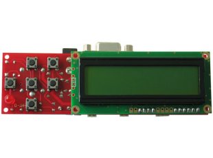
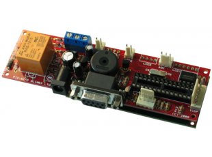
Version three never made it outside of the laboratory. In an attempt to make the system easier to mass produce (ie more than 10), I sought to use an off the shelf development board coupled to a modem such as the Siemens T35. There was a very limited choice of development board available and I looked at using at Olimex PIC-MT. This contained a 16x2 LCD character display, a few user-interface buttons and a relay which could be used to turn on/off power to the sensor. It was still going to be a bit clunky connecting the modem. The world of Arduino arrived before I got too far into version 3.0 and the project moved straight on to version 4.0
RiverSpy v4
I was very loathe to leave behind all of the code that I had developed for the PIC and start again on Arduino but the availability of low cost hardware with onboard GSM/GPRS meant that most of the work was done for you hardware-wise. All that was necessary was to build a simple interface PCB.
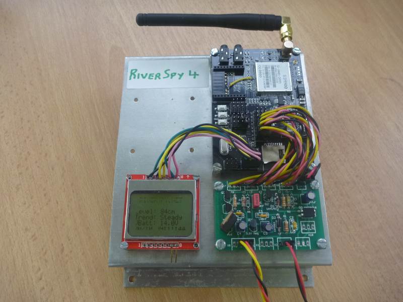
All of live systems are currently using version 4 (as of Oct 2015). A more complete description is given in the Controller Board section so I won't dwell on it here. Version 4 was based on the GBoard 900 Arduino compatible development board. This board includes a SIM900 modem on board as well as a SIM card connector. This board can send its updates to the server by connecting via HTTP rather than sending an SMS. This allows the system to send updates every 15 minutes in an economical fashion. A small Nokia display was added to allow a user interface and an interface PCB (the green one in the image below) was developed with the following function:
- Supply 3.3V to the board to allow it to operate at low power without needing 12V to the barrel jack connector
- Allow the sensor power supply to be turned On or Off using signal A0
- Convert the 0-5V sensor signal to 0-3.3V for sensing at A1
- Use A2 to turn On or Off the 12V supply to the barrel jack when the modem was needed
- Sense the 12V battery voltage using A3
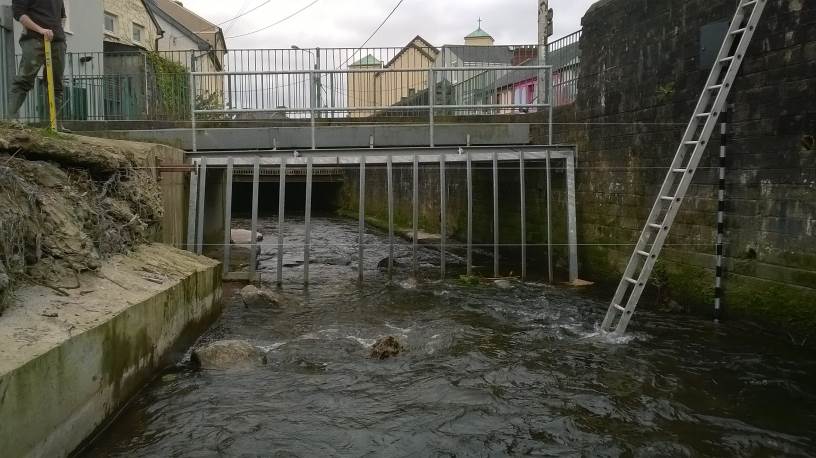
The next image shows a picture of an installed flood warning system near Blackpool in Cork. The 2" scaffold pole mounted on the right hand wall has been painted every 10cm to double up as a stick gauge. The sensor part is dropped down through the centre of the pipe and rests on the bottom. The pipe goes straight into the bottom of the electrical box mounted above the high water mark. The box contains a control board similar to the image above and is powered by 8 D-cell batteries rather than a solar panel. The system measures every 15min but normally only sends updates to the server once an hour to conserve power. When the water level is over 30cm, updates are sent to the server after every reading. If the level goes above 2m, sms messages are sent by the system to warn admins of possible flooding. The batteries need to be changed approx every 6 months. The strings across the river were used to calibrate how many cm corresponded to medium, high and flooding.
RiverSpy v5
At the time of writing this (Oct 2015), version 5 is currently being laid out on PCB. It will be electrically much the same as v4 and will run the same software with only minor configuration differences. The big difference will be in the physical configuration. The board above has lots of individual jumper cables connecting the electronic brick connectors on the GBoard 900 to the interface board and the display. Version 5 will be built as a daughter card which will push onto the GBoard with no interface wires at all. This should make the system very easy to reproduce. Another difference is that version 5 will use the GBoard 800 which has bluetooth built in and has the facility to run from a lithium-polymer battery rather than needing a 12V. The whole system should be extremely compact once complete.